Last time, in 1802 Membership Card Debugging – Part2, I had completed a fully operational 1802 membership card. I had it sitting inside of an Altoids container and I was powering it using a USB TTY adapter with a ground wire connected to the on position. After a while of playing with this, I decided I wanted to go completely mobile. I wanted a self-contained battery operated blinkenlight machine!
On Lee Hart’s page, there are several builds with more robust enclosures. One
looks a lot like an Altair 8800, another is like an elongated Altoids case.
Both were 3d printable and I downloaded them, and I was just about to head over
to the lab on campus to print out one of these cases when a thought struck me.
Everything else about this build is period correct, but 3d printers did not
exist back then! So then I decided I should take one of two approaches, either
build a perfboard frame and mount the card to it, or I should use a plastic enclosure.
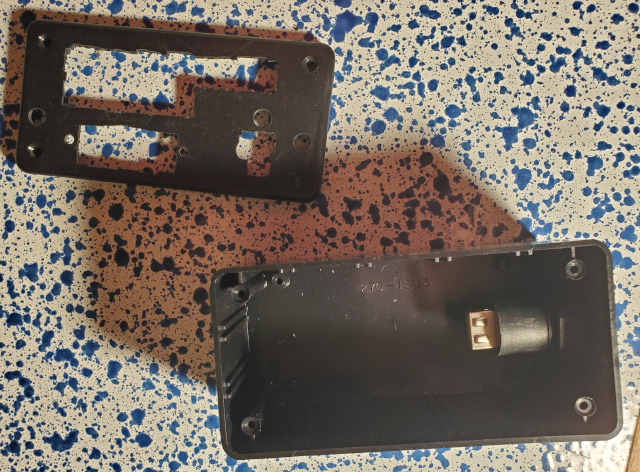
As luck would have it, I actually had a project box in my stash already. It was
part of a selection of boxes I bought from Radio Shack a couple of decades ago.
If I remember correctly, it was a box that had 3 sizes of enclosures, and I had used
both the large and the small one on other projects. The medium sized one was left over,
and as luck would have it was perfectly sized for my membership card!
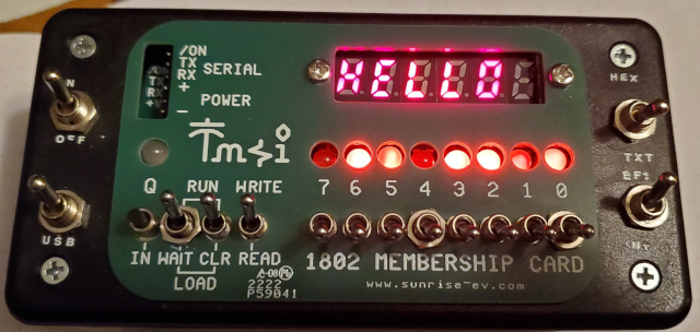
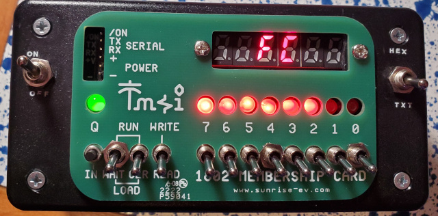
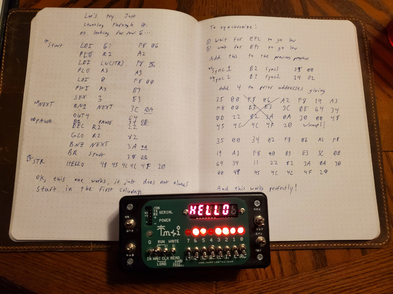
You can see my finished product in the picture above. It has the following features:
- The machine is powered by 3 AA batteries located inside the case.
- The machine can be powered by USB when connected to a computer.
- The display can be toggled between HEX and TEXT displays.
- There is an on-off switch for battery power.
- The USB port can be disabled via a switch.
- There is a switch to direct the display clock to either generate interrupts or to operate pin EF1.
What follows is pictures of my build process and a few notes about how I programmed
my text display for the first time. Some of this was trial and error, and there was
a bit of frustration as I discovered more things that I needed to do, but I am quite
pleased with the results in the end.
Oh yeah! I also fixed that one segment of the display that was not turning on. I had
thought it was probably a bad solder joint. Turns out, I never put any solder on that
pin at all, so that was a quick fix. Ok, now on to the build!
Initial Enclosure and Switches
My initial idea was to attach the membership card to the top part of the box with its
cover card on top. I was going to add two toggle switches, one for turning the
machine on and off and the other for toggling the HEX/Text jumper. I wanted this
second option because I wanted to sometimes program text output and sometimes I
wanted to see the numeric output. Disassembling the membership card to switch the
jumper is tedious, so I opted to replace the jumper with a toggle switch.
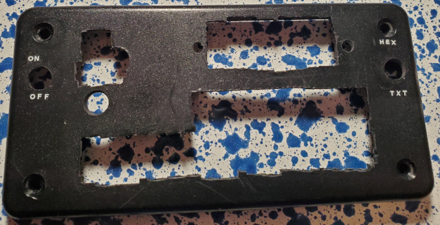
So to make this mounting possible, I used the cover card as a template and marked some
scribe lines for the holes for switches, lights, and the two screw holes. I drilled the
screw holes, and then I used a nibbler tool to cut the square holes. Initially, I made
things pretty neat and straight. I wanted to match the cover card exactly, but when I
test fit the card I realized that this made the switches and lights sit far down
into the card. So I widened the holes so that the toggle switches and lights could
protrude above the plastic. As a result, I also removed the headers for the 30 pin
port on the front panel card so that it could sit flat against the inside of the cover.
I figured my rougher cuts would be covered by the cover card, and it was. In fact,
sitting like this it looks much better than when it was farther down!
I also drilled holes for my two new toggle switches (On-Off and HEX-TXT).
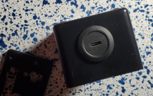
Another goal that I had was to have a simple integrated USB serial port. I have a bunch
of these that I bought cheap on AliExpress a while ago, and I knew they worked well with the membership
card. To integrate it into the case, I used Adafruit Part #4259: Panel Mount USB C to USB A Jack. I drilled a hole in the case and installed this, making sure the internal port was upside down. (It stacks better that way.)
So now I’ll have a USB C membership card!
I finished off this stage of my case preparations by putting some dry transfer lettering
in place to label my switches. I think the last time I used dry transfer decals was back
in the 1980s, and you can clearly see that I was out of practice. In spite of putting down
a masking tape line, I was still a little crooked. Oh well, that’s just some more hand built
charm!
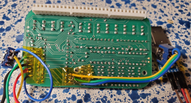
Now that I had the enclosure ready to go, all that was left was to connect the
battery holder and the switches! I did this by soldering to the underside of the pins
to be connected. This left the serial port pins open at the top so that I could
connect other serial devices. For the jumpers, the clearance just wasn’t enough to use
jumper wires. I covered these joints and secured the wires with a bit of kapton
tape. This felt appropriate because both kapton and the COSMAC 1802 are frequently
used in spaceflight! It’s also a very thin insulator, so that worked out perfectly.
The on-off switch connects ground and the on pin to the battery ground. I put the
battery ground on one side of the switch, and the other two on the others. This means
that when the switch is in the off position, the battery is disconnected leaving the
memory backup to the super capacitor. I know I could have made the battery always
connected to ground, but I opted against that because I had already installed a capacitor
to back up the memory!
With all this in place, I was ready to put the pieces together and test it out.
Built-In Serial Converter
My initial plan was to run off of batteries exclusively. So I simply connected the
ground from the serial port to my On and Ground on the membership card. This was so
it could act as a signal ground. So I put the batteries in the bottom of the case. I
then wrapped the serial adapter in kapton to keep it from shorting to the batteries or
the circuit boards mounted above it and set out to put everything together.
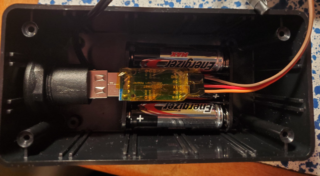
When I did, I discovered it was a fairly tight squeeze. I realized that turning the
panel around so the USB port was on the right made the wires fit a bit better, so
I went with that. I turned it on, and the board lit up! So I screwed it down and started
to play with my battery operated computer.
As I started to toggle in my first program, I noticed that the Q light was green,
indicating that it was receiving data from the serial port. I tried a few things to
see if I could turn it off. I tried the Q-blink program, and it toggled between green
and orange. I took the front panel back off and realized that the USB adapter’s power
LED was dimly lit. A little more checking revealed that there was a slight potential
difference between RX and Ground, even with the USB port disconnected. I’m talking on
the order of 1/10 of 1 mv. This was just enough to wake up the USB adapter and cause it
to enter a weird state where it is constantly transmitting.
To fix this problem, I decided to allow the USB adapter to participate in powering the system. I put a couple of Schottky diodes in series with the positive leads of both the battery
and the USB adapter. This would “OR” the power supplies together. It would also, hopefully,
eliminate this things propensity for powering itself from its RX pin, and it sort of did.
This made it intermittently send something to Q. Ultimately, I decided to add another switch.
This one would cut the ground to USB in the up position and enable USB in the down
position. I connected this switch to the ground position with the membership card’s
ground and the on switch. Thus enabling USB with USB plugged in would power the
device and turn it on. So when this switch is down, this is a nice little USB accessory!
Text Programming and Final Configuration
Ok, so now we are up to three switches. The astute reader will notice that the image on
the opening graphic has 4 switches. Here is the story of that fourth switch!
So now that I had a working self-powered 1802 Membership Card, I decided that I wanted
to make all those extra 7-Segment displays do something. In particular, I wanted to see
them say “HELLO.” Unfortunately, the manual had nothing about doing this. I knew
that if I flipped my switch to “text” and then sent an ASCII character, the character
would appear on all six displays.
Looking at the schematic, I saw that there was a 400Hz clock which feeds a counter.
This counter determines which of the commons will be on, and so I surmised that the
membership card displays only one character at a time with a 2.4Khz frequency.
Our pathetic little mammal brains see this as a constant display. Ok, so then I just
had to know how to synchronize with the clock. A little more investigation revealed
that Row 6’s clock is plugged into the counter reset as well as into EF2. So then
what I decide was to do this:
- Wait until EF2 goes low.
- Wait 1/400th of a second.
- Display the fist character.
- Delay for the remainder of 1/400th of a second.
- Repeat 3-4 until EF2 goes low.
- Go back to step 2.
In short, I was going to sort of bit-bang my way through output to this thing.
I actually made this work! The way I did it was by observing that we have 4MHz clock,
with 8 clocks per machine cycle. This means there are 500,000 machine cycles per second.
Each character is comprised of 1,250 cycles. All one must do is synchronize on
the Ef2 signal and then write some carefully calibrated loops by counting machine
cycles in each instruction. I thought “Why not? After all, I have written VCS code which
is much worse!” Upon further reflection, however, I realized that there is something
else going on.
Studying the schematic further, I noticed that there is a connection to P9 from the
400Hz clock. P9 then connects to INT, thus triggering an interrupt at each clock pulse.
P9 is left off of the construction of the board. I briefly though about adding a header
and jumper here, but then I realized that would mean that every program on my 1802 would
need to respond to this interrupt. I went searching the web for guidance, and I came across
this discussion. One respondent
recommended connecting instead to EF1. I noticed that nothing is connected to EF1 on
the schematic, and so I added a fourth toggle switch! If set to its up position,
this switch will route the 400Hz clock to EF1. If in the down position, it is sent to INT.
Thus I can have a character output interrupt or I can have an EF1 based one. More importantly,
I can run other membership card software without wrapping an event handler into it.
(This is especially important for running from the ROM!)
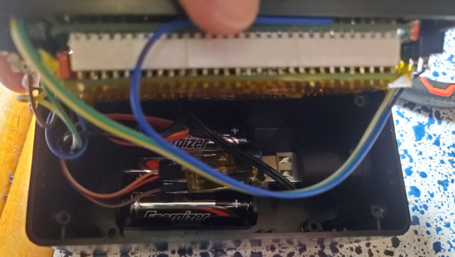
Ok, so with the fourth switch in place, I was ready to close things up. I noticed that if I
squeezed the case a bit, there was a tendency to short across the input button and
mess up the memory. So I decided to laminate the bottom of the CPU board in kapton tape
and then carefully route the wires as I put it all together.
And now, I was ready! I set my switch to EF1 and wrote an EF1 signal based version
of a string display which cycles through six characters. That program, and its output
is below.
Oh my goodness was this so much easier! My timed loops method was so frenetic, and
left so little time to do anything else. If I switched over to an interrupt based
model, it would be even easier! I will do that another time though.
Thus ends my lengthy, and quite enjoyable, build of this kit. I have written
several programs for my membership card, and I can’t help but to have fallen in
love with the 1802. I can now curl up with my notebook and toggle in some
hand-assembled programs, or I can plug in and run the ROM Monitor to load things
from a cross assembler. This is truly the most flexible blinkenlight box I have
ever owned!
Next time, we’ll do some coding in either ASM or BASIC. In the mean time, buy
and build your own 1802 membership card!
 Computers
|
Home
|
Humor
|
Links Computers
|
Home
|
Humor
|
Links
|