The Fix
Last week, in 1802 Membership Card Debugging – Part 1, I had gotten as far as determining
that while the CPU was running, the latches were not latching the
output port or the address. Then I got to thinking about the testing
I was doing. I was following the pinouts listed in the schematic in
the membership card manual, and so I did not notice that something was
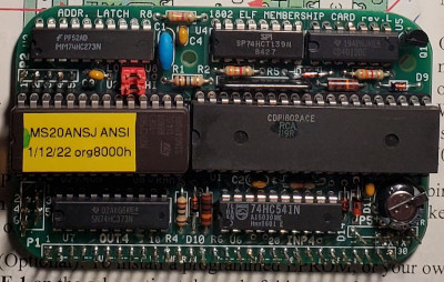
different between the two chips. They were not, as I had thought, two
latches! One is a 74HC273 positive edge triggered octal D-Flip Flop
while the other is a 74HC373 transparent D-Latch. Similar ICs to be
sure, but they have different operating characteristics.
Actually, I should have thought about this when I saw the O-Scope read
out. It’s clear they are not receiving the same timing signals. I read
the instructions about a dozen times while assembling this, and I had
completely missed the part number difference. I also did not notice it
on the board or on the chips themselves. Worse, I had them swapped!
So it
looks like the thing I warned myself about back in
1802 Membership Card Build has come to pass. I had to do
some desoldering on this tiny board. Luckily it was on the ICs and
I was able to get the solder off fairly quickly with my handy
desoldering iron. I had a little mishap with both chips though.
I broke a pin off of one and the other just would not let go and wound
up getting broken in half. Argh!
So I put in an order to Jameco for a replacement. The pair together
came to about $1.70. Jameco has a minimum order of $20.00 without
a fee, so I bought a few odds and ends to bring my total above $20.00.
(Hey, I can always use more wire, solder, posts, jumpers,…)
The replacement chips arrived today, I soldered them in place, and
bingo! Everything works!
Exploring the 1802
So now I have a working 1802 computer and I can enter programs and
view them on the front panel. So then I had to a little bit of
exploring. As one does with a blinken-light machine, I set to work
writing a program to sweep the lights back and forth Knight Rider
style!
This took a while because I have never coded for the 1802. As
I started to explore, I realized just how different this processor is
from other early micro processors. It has a plethora of registers,
with 16 address registers which can be accessed via their high and low
bytes. These function like 16 pointers into memory, any one of which
can be used as the program counter. There are two registers, X and P,
which indicate which of the 16 will be used for I/o and program
counting respectively.
A little bit of a read-through of the manual plus the little fold out
card reference for the instruction set was all I needed to set to
work. I knew that the lights lived on output port 4. I decided to use
R2 as a counter to delay the motion of the lights as was done in the
Lee Hart’s slow blinking example. I was originally going to store the
output byte in the high part of register 3, but then I realized there
is no way to do register to port output. Rather, I/O appears to mainly
be register-indirect memory access. This is definitely a processor
designed to sling bytes around in memory!
So I reworked my program a bit more. I decided to store the display
byte at 0x00FF, and then access it via register 4. My initial attempts
had weird behavior until I realized that the OUTn instruction actually
increments Rn after doing output. This is so you can very easily copy
bytes out. (Weirdly INn does not seem to increment!) So I added
a decrement after each OUT.
When it came time to design the logic, I realized that the shift left
and shift right instructions only differ by 1 bit. So I made the
program perform an ANI operation against the byte 0x81 and if that was
non-zero I flipped the bit in the instruction. So this is a bit of
self-modifying code. Dangerous, but short!
Oh, and did I mention I did all this by hand?
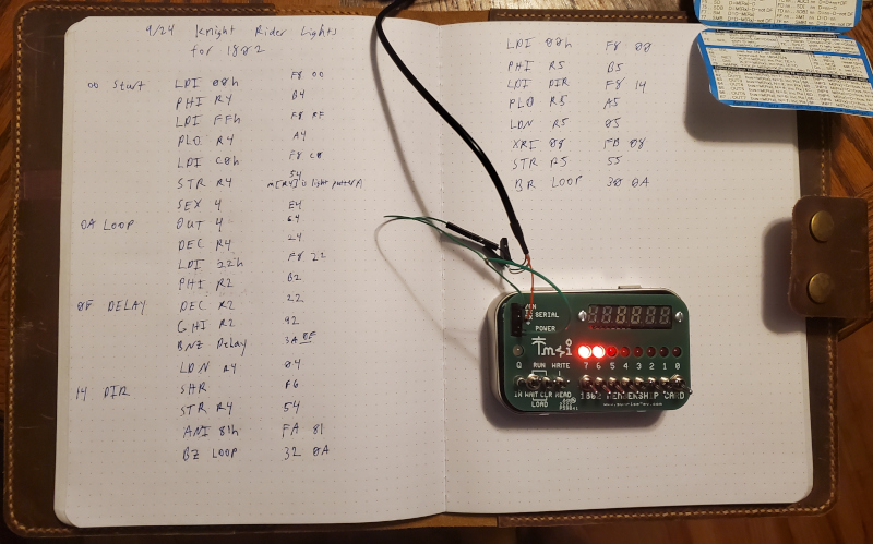
After my little bit of hand assembly, I toggled the program in via the
front panel, and thus was another blinkenlight gif born:
Of course, a keen observer will note that there is one segment out on
the displays. Probably just has a faulty solder joint (those were
pretty tight.) I will fix that on another day.
Oh, and one other thing. I did test out the ROM. I had a little bit of
trouble getting my terminal connected, but I did eventually get the
monitor up and was able to run some BASIC programs. But I think I will
write about that in another post.
Now to add my new blinking program to my CS castle. Thank you for
reading along with my little adventure. I am going to keep playing
with the 1802 and I’ll post some more programs and thoughts soon!
UPDATE: I finalized my build with a nice little enclosure and a few more toggle switches. You can read about my final build here: Finishing My 1802 Membership Card.
 Computers
|
Home
|
Humor
|
Links Computers
|
Home
|
Humor
|
Links
|